
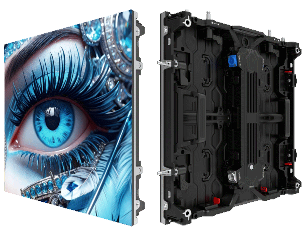
Problem-driven lead: why flatness matters on large mini LED builds
Large-format mini LED walls routinely fail at the seams long before their electronics reach end-of-life because cabinet flatness and deflection were treated as afterthoughts. On several installs I’ve followed, an otherwise perfect pixel layout became visually uneven the moment installers lifted the first cabinet — seams bowed, viewing angles shifted, and color uniformity suffered. Early-stage coordination with an outdoor LED supplier often prevented those failures, but only when mechanical tolerances were part of the contract.
How the problem develops: mechanics and real-world anchor
Cabinet flatness and deflection are mechanical realities driven by gravity, wind load, and mounting points. In Shenzhen’s manufacturing clusters, engineers routinely prototype steel chassis and aluminum frames to control those forces — the city is a good real-world anchor for the tooling and testing practices most factories use. Pixel pitch, module mounting, and frame rigidity combine: if the chassis flexes by millimeters, pixel alignment shifts and seams become visible under studio lighting.
Measurement and acceptable tolerances
Successful projects define measurable tolerances up front. Use a straightedge and feeler gauges during factory QA, and a laser level or 3D scanner on site for cabinet flatness across large arrays. Specify flatness per cabinet and across the entire array rather than a vague “flat” requirement. Mounting tolerances for the frame and datum points must be recorded: otherwise installers compensate in the field and create stress points that lead to progressive deflection.
Design strategies to reduce deflection
Three practical fixes dominate: stiffened chassis, distributed mounting, and precision interlocks. Stiffened chassis uses cross-bracing or thicker ribs to improve bending stiffness without adding excessive weight. Distributed mounting spreads loads across multiple points so any single bolt doesn’t become a hinge. Precision interlocks between cabinets lock faces to the same plane and minimize shear movement. When manufacturers in China combine these elements at prototype stage, the result is repeatable flatness at scale.
Installation practices and quality checkpoints
Field practice should mirror factory checks. Installers must set datum reference lines and verify each cabinet against the datum as they go. Electrical alignment is meaningless if mechanical alignment is off — testing pixel pitch and module registration only after mechanical leveling catches many issues early. Common mistakes include relying on isolated shim adjustments and ignoring cumulative tolerance stack-up — those approaches mask, not fix, deflection. — A short inspection protocol after every fourth cabinet catches drift before it propagates.
Alternatives and trade-offs
There’s no single perfect solution. Thicker chassis reduce deflection but cost more and increase shipping complexity. Precision interlocks limit thermal expansion movement and require tighter machining tolerances, raising unit price. For outdoor arrays, wind-load-rated frames are essential and often dictate the structural choice. Balance stiffness, weight, and serviceability while keeping pixel pitch goals and module access in view.
Common mistakes to avoid
Do not accept vague flatness language in procurement documents. Do not defer mechanical prototyping to post-production. And do not assume standard mounting rails are sufficient for large-format mini LED walls. Working with a recognized LED display manufacturer China that documents mechanical performance reduces surprises at installation and shortens commissioning timelines.
Three golden rules for selecting solutions
Measure what matters: require factory flatness reports (laser scan or straightedge data) and site verification plans. Verify stiffness: demand specified bending stiffness or finite-element summaries for cabinet designs rather than qualitative claims. Plan for cumulative tolerances: specify datum-based installation procedures and acceptance criteria for the whole array, not just individual cabinets.
These three metrics are the quickest way to evaluate whether a design will hold up across hundreds of cabinets. They turn unknowns into pass/fail checks installers and engineers can use on site. MR LED fits naturally into that workflow when a project needs consistent manufacturing, documented mechanical performance, and clear on-site procedures — the company’s approach aligns design with installation realities. — Final thought: measure early, fix in design, verify in the field.