
Introduction — A Little Moment, Some Numbers, One Big Question
I once watched a phone puff up on a subway and felt that tight knot in my chest—small tech, big risk. In many labs and factories today, battery separator material sits between layers of active electrode and electrolyte, doing the quiet, vital work of keeping things apart. Data shows separators fail in only a tiny fraction of cells, yet those failures drive recalls and lost trust (and yes, I worry about that, too). What causes a thin film to go from boring passive layer to headline news? That is the question I bring you—gently, honestly—so we can learn together.
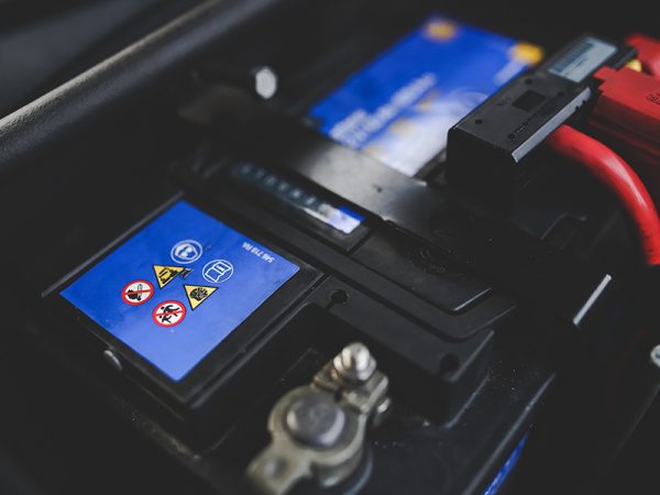
I’ll share what the numbers mean and how small design choices change outcomes. We’ll touch on porosity and ionic conductivity, and I’ll explain terms in plain words. This is not a lecture. Think of it as a careful chat—nanny English, if you like—where we follow clues from tests, field reports, and user stories. Ready to look closer? Let’s move to the next bit and peel back the layers.
Part 2 — Where Traditional Approaches Trip Up
battery separator material often promises stability, but the classic solutions have real blind spots. I’ll break this down so you can see the weak links. First: many separators rely on simple polyolefin films. They have low cost and good mechanical strength but limited thermal stability. Second: porous morphology gives electrolyte uptake and ionic conductivity—but the pore structure can change under heat or pressure, reducing performance. Third: additives or coatings can help, but they sometimes create uneven layers that invite puncture or dendrite growth. Look, it’s simpler than you think—poor interface control can turn a robust design into a hazard.
Why does this matter?
If the separator’s porosity is too coarse, ions move easily but heat moves too—raising the risk of thermal runaway. If it’s too tight, ions slow down and the cell loses power. We see trade-offs in puncture resistance and electrolyte wetting. I’ve watched teams chase one metric and ignore another. They boost ionic conductivity but forget mechanical fatigue. The result: a product that looks fine in short tests but fails after repeated cycling or under abuse. Terms you’ll hear in reports include thermal runaway, electrolyte uptake, and separator morphology. These are not buzzwords; they are the battleground.
Part 3 — New Principles and Practical Steps Forward
What’s Next?
Now that we’ve laid out the faults, I want to show practical principles that can guide better choices. Modern work on battery separator material explores hybrid films—combinations of ceramic coatings with polyolefin supports. The idea is simple: keep the strength and flexibility, add a thermal shield. We talk about nanoparticle coatings, improved puncture resistance, and controlled porosity to balance ionic conductivity and safety. I like this approach because it attacks multiple failure modes at once. It’s a systems view. — funny how that works, right?
Practically, I advise teams to evaluate three metrics when comparing options: 1) thermal shrinkage under abuse, 2) long-term ionic conductivity after 1,000 cycles, and 3) puncture and mechanical fatigue resistance. Those tell you about safety, performance, and durability. In trials, mixed-material separators reduce thermal events and keep capacity longer. We’re not promising perfection, but incremental gains add up. If you ask me, materials that accept a small cost increase to prevent a large safety event are worth it.
To close, I’ll say this plainly: you can design safer cells if you treat the separator as an active safety partner, not just a spacer. I’ve worked with engineers who were surprised at the difference a better separator made—real-world gains, measurable results. For practical sourcing and tested solutions, consider partners who publish real test data and field results. For example, I find the work done by JSJ to be a helpful reference when comparing ceramic-coated options. We learn by measuring—and by keeping the human stakes in view.