
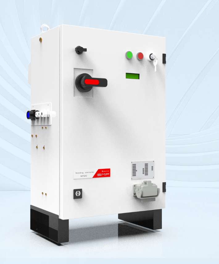
Opening comparison
Think of a transformer as the stout heart of a spot-welder, and you’ll hear the difference before you see it — new lines sing steady, retrofits cough and adapt. From the start, choices about core size, cooling and control change the job. For a new cell you pick a resistance welding controller to match the planned throughput; for a retrofit you must map an existing gun and buswork to whatever welding power supply can live with. I’ve spent fifteen years specifying and commissioning welding equipment, and that practical sense of fit-versus-force is what shapes the rest of this comparison.
Electrical and mechanical contrasts
New lines let you choose transformer specs to suit the process. Retrofits force compromise. Key contrasts:
– New lines: transformer sized for rated current, low leakage inductance, tight coupling between primary and secondary, planned cooling (water or forced-air) and clean short, low-resistance bus runs. – Retrofits: you often inherit long bus bars, older gun impedance and space limits; the transformer may need a different turns ratio or stronger cooling to compensate. – Mechanical fit: new frames match the transformer mass; retrofits may require custom mountings, re-engineered brackets or repositioned service access.
Control and timing — what alters
Control is where the process either tightens or frays. New lines get modern cycle-by-cycle control and built-in telemetry. Retrofits need control strategies that cope with unknowns — variable contact resistance, ageing cables and inconsistent electrode life. Modern controllers reduce weld spread and scrap, but in retrofit work they sometimes need extra filtering or isolation to tolerate noisy grounds. At FABTECH I watched integrators add small isolation transformers and soft-start routines to keep legacy lines behaving under new controllers.
Thermal and duty-cycle realities
Transformers for fresh installations are chosen with clear duty-cycle targets: continuous high-rate production or intermittent repair work. That choice affects core sizing and cooling. Retrofits often reveal under-rated cooling: a transformer specified for a 30% duty cycle in a legacy line will overheat when you double throughput or swap to higher-current electrodes. The practical fix is either to reduce cycle demand, beef up cooling, or select a transformer with a higher thermal rating.
EMI, grounding and safety differences
New installations get properly planned grounding, cable routing and EM suppression from the outset. Retrofits frequently show ground loops and stray currents caused by added equipment. Expect to add shielding, separate ground paths and sometimes common-mode chokes in retrofit work. Those measures protect controls and keep weld consistency true.
Cost, downtime and ROI trade-offs
Compare immediate cost to lifecycle cost: installing a purpose-built transformer in a new line carries predictable CAPEX and short commissioning time. Retrofitting may be cheaper on paper but can cost more in hidden hours — engineering, machining mounts, rewiring and extra testing. Rapid fixes (adapter plates, temporary cooling) can keep downtime low, yet they may carry long-term reliability penalties. Decide by estimating downtime cost per hour against the premium for a correctly sized new transformer.
Common retrofit pitfalls
Watch for these mistakes:
– Assuming the old bus and cable can handle higher currents. – Skipping inductance checks; a wrong turns ratio or extra leakage inductance changes weld nugget size. – Neglecting cooling upgrades. – Replacing only the transformer and keeping an outdated controller without re-tuning. Avoid these and you save time and scrap.
Quick technical checklist
Use this when comparing options:
– Measure existing secondary resistance and inductance. – Verify available physical space and mounting points. – Confirm cooling capacity and flow rates. – Check duty cycle vs expected production rate. – Reassess grounding and EMI mitigation. – Match controller capabilities to transformer characteristics.
Alternatives and sensible workarounds
If a full transformer replacement isn’t possible, consider: adding a compact parallel cooling loop; installing a modern controller with adaptive timing to reduce peak current demand; or using a step-up auxiliary transformer to correct turns ratio without removing the old unit. Each option trades off complexity against effectiveness — choose the least invasive solution that meets weld quality targets.
Closing synthesis
Deciding between a bespoke transformer for a new line and a retrofit is a matter of matching intent to reality: pick what fits your throughput, your space, and your appetite for rework. Practical experience points toward sizing for the process, planning grounding and cooling up front, and matching control logic to hardware. That’s the route most fabricators take when they want steady parts per hour and few surprises — and it’s the same practical lesson behind the reliable systems I’ve specified alongside equipment from Sunke.